By Bruce McCalley
During the early '30's my father, who worked for the telephone company, began repairing radios to supplement the family income. He has an agreement with one of the local radio stores in which he could sell their radios on some sort of commission basis.
About 1931 Dad sold a Sparton Model 301 to a customer who at the time apparently had a good income. The set sold for about $300 which was a lot of money back then. As the story goes, this customer lost his job and ultimately sold the Sparton back to Dad for just $15.00! This radio became the "family" radio until about 1939 when a table model Philco sort of took its place.
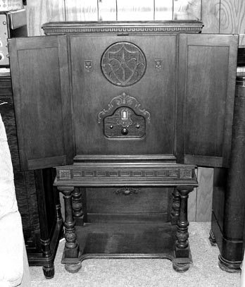
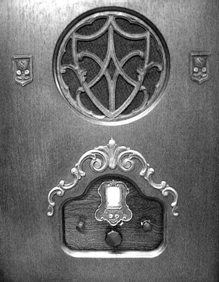
The front panel of the Sparton 301 console cabinet
The Sparton remained in the front room of the house for years afterward but with the advent of television, it was seldom used. In time Dad removed the chassis and converted the cabinet into sort of a china closet. The chassis was stored on a shelf in the garage where it remained until sometime in the 1960's
One day I decided it would be interesting to restore the old set as so retrieved it from its resting place. Sadly, by that time the original cabinet had vanished, as well as the original speaker, but I went ahead anyway and began searching for a cabinet and speaker.
Years went by. In the meantime I modified the chassis by installing an output transformer (the original was part of the speaker) and using a 5000-ohm resistor in place of the speaker field coil.

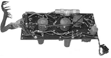
The Sparton chassis assembly. The three units (tuner, RF amplifier, and power supply-amplifier) are bolted to a wooden base board. Antenna and ground connections are spring-loaded clips on the top left of the tuner. There is a trimmer capacitor next to these connectors which must be adjusted for makimum volume whenever the antenna is changed. The "ground" connection here is a small capacitor connected to one side of the power line.

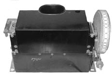
Rear view of the same chassis. The '50 audio output tubes are on the left and the '81 rectifiers are on the right. The small transformer between them is not standard equipment. It is the output transformer needed because of the lack of the original which was located in the speaker assembly. The tall box in front of this transformer contains the filter capacitors. The originals have been replaced with oil-filled 1000 volt paper types inside the original box. The small adjustible coil at the left just behind the RF amplifier box is a trap to eliminate the 10 kHz beat between stations, unusual for a receiver of this age.
The Sparton, like many other receivers of the day, used a "power detector"-or plate detector, or one of the other names for this circuit where the cathode resistor is of a very high value making the tube non-linear and therefore acting as a detector/ amplifier. The problem with this circuit is that unless the signal strength at the detector is somewhat large, there is considerable distortion in the detected audio. Since the volume control is this set varies the gain of the RF amplifier, distortion at low volume was a problem.
To solve this problem I added a small capacitor in series with a diode (1N60 in this case) between the last coil and the grid of the old detector tube, a 100K resistor from the grid to ground with a 100pf capacitor across it, and changed the cathode resistor to 2200 ohms. In addition I removed the two original .002 mF bypass capacitors in the plate circuit for better high-frequency response.

Top view of the power/amplifier chassis. The ceramic sockets are replacements for the original phenolic types, one of which caught fire. The terminal board on the left is where the RF amplifer and turner cables connect, as well as the front-panel volume control. The oval-shaped box just below the power transformer contains two house-type screw-in fuses. The terminal strip just to the left of the fuses is the AC voltage selector. The capacitor and wire connected there are the "ground" connection.
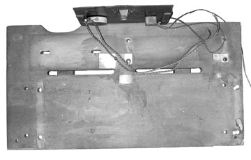
This is the wooden base which holds the three receiver units. There are two metal strips that form the ground connection between the units. There is no other common ground so it is important that these be effective. When servicing the set it is important to connect the metal chassis together, not only to operate but to prevent electrocution of the serviceman.
Undersideof the RF amplifier chassis. The chassis is a phenolic board, not metal.

Top view of the RF chassis, now mounted in its metal box.
The tuning unit. The original 301 did not have the tube. This modification in the design apparently appeared about 1930 and greatly improved the selectivity and sensitivity of the Equasonne Spartons.
It sounds just great; better than most of the old radios I've had!
Years passed. My search for a cabinet ended when I located a set in Seattle. The owner
said he could get it to Portland. I had another friend who was going to Portland and could
then bring it to Hayward, California. I drove to Hayward.
The chassis in this set was almost beyond help but the cabinet was in pretty good shape,
so I was happy. One week later, at a SCARS swap meet, an identical cabinet (with a lesser
Sparton chassis) showed up at half the price! I bought it as well!
I have found an original speaker but its cone is missing. Without the cone, it is not
too effective!
The design of the Sparton Equasonne was unique. To my knowledge no other manufacturer
used the pre-selector followed by a broadband amplifier system such as this one.
(Early superheterodynes used a similar amplifier but at a much lower operating frequency.)
Not only was the system unique, but the selection to tubes used and the heater voltages
of those tubes was also unique.
The Equasonne system was discontinued about 1932. With the release of the superheterodyne
patents by RCA, Sparton introduced an entirely different line of chassis, mostly superhets,
which then used standard types of tubes.
Following is a brief description of some of the Cardon tubes used in Sparton Equasonne radios.