The June 1931 issue of Radio News featured an article on the then-new Scott All-Wave receiver. The writer obtained one of these sets and took it to the suburbs of New York City for a "trial run." The article went on to extol the virtues of the new Scott, recounting the many distant stations received with ease, mostly on the broadcast band. A second part of the story continued in the July issue, with equal enthusiasm. Prior to this model all Scott receivers were to the tuned-radio-frequency type due to the RCA license restrictions on the use of the Superheterodyne circuit. When RCA allowed the use of its patents on the circuit in 1930 most of the major manufacturers scrambled to bring out a Superheterodyne model, and Scott was no exception.

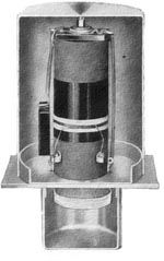
Plenty of shielding and a chrome-plated chassis
The model featured here lasted less than a year. The use of plug-in coils for the various bands severely limited the appeal of the receiver and Scott came out with a new design with band-switching in 1932. That set was the basis of all top-of-the-line models until the introduction of the Philharmonic models several years later.
The writer, S. Gordon Taylor, marveled at the excellent tone quality of this new Scott. By today's standards it would be considered somewhat typical of that era-the selectivity of the set severely limited audio response above about 5000 cycles.
Following is Mr. Taylor's comments and description of the receiver.
"When the set was turned on, this enthusiasm instantly took a jump, because of the fine tone quality that was apparent with the first few bars of music tuned in. Although the loud speaker was set up without a baffle, the quality of reproduction was really impressive in its depth and timbre.
"Regardless of the setting of the volume control, this excellent quality persisted. due partly to the use of power detection in both first and second detectors and to a push-pull arrangement of tubes in both the first and second audio stages and not overlooking the complete shielding and the resulting stability in both the radio and intermediate-frequency amplifiers.
Circuit diagram of the Scott receiver chassis
"After listening a few minutes to this station, which we had assumed to he a local station. it was announced as WMAQ. Chicago. Of course, we had expected to bring in Chicago stations without any difficulty but to have one come in without any background noise whatsoever, and with all the earmarks of a local station so far as both quality and volume were concerned, was a distinct surprise which provided thrill number three for those listening in."
Taylor's Description
The Scott receiver employs a total of twelve tubes. As indicated in the circuit diagrams five are of the -24 type and are employed in the r.f stage, first detector and three intermediate amplifier stages. Four -27's are used for the oscillator, second detector and the push-pull first audio stage. In the output power stage two -45's are used and a type -80 rectifier is included in the power unit.
The receiver chassis includes the receiver up to and including the first audio stage while the power output stage is included in the separate power supply unit. The loud speaker constitutes the third unit. It is only the work of a moment to connect up the three units, all connections being provided in the form of cables and plugs. Once connected up, the power supply to all units is controlled by a separate switch, also provided, which can be attached to the outside of a cabinet.
Tuning
Tuning is accomplished by means of two drum dials. One controls the RF and first detector tuning condensers, which are ganged. The other tunes the oscillator. For short-wave reception plugging in the proper coil for a given band automatically connects in the short-wave tuning condensers to correspond with the coils. To avoid the complications and inaccuracies of ganged condensers on the short waves the RF stage is tuned only in the broadcast range. For the short wave bands the RF stage is untuned and is coupled to the antenna by means of a choke coil, thus leaving only one tuning condenser to be controlled by each dial. This results in maximum efficiency and precision in tuning, features which are of the utmost importance in short-wave work.
Other Controls
Two other controls are provided on the front panel. The one at the left provides three degrees of antenna coupling as indicated by the tap switch on the antenna coil primary in the circuit diagram. As a means of providing any desired degree of selectivity this arrangement works out to excellent advantage. Normally the center tap provides ample selectivity under practically all conditions. but where interference is particularly severe, as in the immediate vicinity of a powerful station, the lower tap provides the super-selectivity required.
The other knob is a volume control which is extremely smooth in operation and provides very gradual variation—an important feature.
Provision is made, in the form of two binding posts on the rear edge of the chassis, for connecting in a phonograph pick-up or microphone. A separate control box for phonograph and microphone switching is available.


The power supply and audio output chassis and schematic
A study of the receiver circuit diagram and the power-unit circuit will provide detailed information on the many worth-while features incorporated in the design of which space does not permit a detailed discussion. One feature especially worthy of mention, however, is the design of the intermediate-frequency transformers. One of the complications of screen-grid circuits is the necessity for providing high-impedance transformer primary circuits in order to approximate the output impedance of the tubes—that is, if good efficiency is to be obtained. On the other, hand, a large primary winding, or a tuned primary is likely to provide a degree of coupling that mitigates against adequate selectivity.
In the Scott receiver this problem of obtaining high efficiency and ample selectivity at one and the same time is solved by inclosing the primary and secondary of the transformer in separate, individual shield cans, providing complete shielding from one another. The coupling between the two is accomplished by winding a relatively small coil directly over the secondary winding. This winding is then connected in series with the primary. The degree of coupling thus may be small, depending on the size of this pick-up coil and its location on the secondary winding, without sacrificing the desired high primary impedance. This design, in addition to providing any desired degree of selectivity, also tends to increase stability.
Construction of the IF transformers
The receiver covers the entire broadcast spectrum, from 15
meters up to 550 meters, except for a small gap between 184 meters and 200,
which contains nothing of interest for the broadcast fan. Six pairs of plug-in
coils are used for the purpose. These cover the following ranges:
The tuning capacity employed with the short-wave coils is much smaller than that employed with the broadcast coils. In the case of the coils for the lowest wave-bands still smaller tuning capacities are employed. The shift from one set of tuning capacities to another adds no complications in operation, however, because the changes are made automatically. Each coil as it is plugged in makes its own connections to the proper capacities.
One of the features stressed by the manufacturer is the treatment of coils to protect them from the effects of moisture. Along the seaboard and particularly in some tropical areas this feature is an important one. The unusually complete shielding of the whole receiver is another safeguard against damage resulting from exposure to humidity, of course, but the coils not in use and therefore not in position within the shields need the protection provided by the special process of dehydration and impreg-nation to which all Scott coils are subjected.

View of the under-side of the receiver chassis. Note the simplicity. Major components are inside shielded cans.