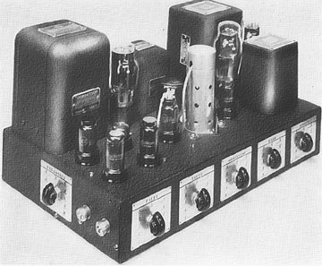
THE RADIO NEWS 1940 FULL-RANGE AMPLIFIER
By Bruce McCalley

This writer's interest in "high-fidelity" began shortly after my interest in radio itself; about 1938. High-fidelity in those days was a distant dream for most of us. Records were quite limited in frequency range and volume level. Radio programs were often recorded and even the live ones were lacking the quality of an in-person performance. I remember marveling at the quality of movie theater sound compared with what we had at home and am astonished at how poor even that was when compared with that which we have today.
I became acquainted with Fred Darugh, who worked for my father at the telephone company in Van Nuys, California. Fred was really in to the high-fidelity field and made money on the side by playing records for various dances in the San Fernando Valley. I was just a boy at the time but phoned Mr. Darugh (adults were always mister or missus when I was a boy) almost every night asking questions about almost anything in radio. Even today I wonder at his patience and understanding. I owe him a lot.
Fred's amplifier used push-pull parallel 2A3's in the output and had a volume expander circuit using a 6L7 (common in those days). I remember the almost-constant experimenting with the expander circuit. He copied the RCA circuit, then the Scott system, settling on the latter. The bias settings for the 6L7 were somewhat critical for the expander to really "expand" and the Scott system seemed to stay "in adjustment" for a longer period. With each change Fred made, I incorporated in my own amplifier. I used push-pull parallel 45's instead of 2A3s; they were easily available from my Dad's tube supply. (Dad repaired radios during the early part of the thirties and had a large box of tubes left over from that period.)

In the December 1939 issue of Radio News the major feature was the 1940 Full-Range Amplifier by Oliver Read and Karl A Kopetzky. Read was the Technical Editor, and Kopetzky was the Managing Editor of Radio News. The article described the ideas behind the design, and the ends which they hoped to achieve. The article continued in the January and February issues of 1940.

The first design of the Radio News amplifier
The amplifier used push-pull 6A3's (six-volt versions of the 2A3) driven by a transformer-coupled 6C5. The 6A3s were fixed-biased by a separate rectifier (an 80) with separate bias controls for each tube and provisions for metering the plate current of each. Inverse feedback was also used on the output stage. Bass and treble control was by means to the Thordarson-designed system in which a choke was used in the bass circuit and capacitors in the treble circuit, using a 6C8 dual triode tube. The tone-control stage was preceded by the volume expander circuit using a 6L7, 6C5, and 6H6. The expander stage was preceded by another 6C5 for phono operation and a 6SJ7 microphone stage. A 5Z3 was the main rectifier.
The interesting part of the expander circuit was that the signal for the 6C5 expander amplifier got its signal after the tone control circuit (the grid of the 6C5 driver tube) instead of before the 6L7 expander tube. This would appear to make it sort of a run-away method in which the volume expansion would keep "expanding" by itself but I've never tried it.

The second design of the Radio News amplifier
The circuit was modified in the January 1940 issue. It now used a 6F8G (dual triode) as the driver and another 6F8G in the modified Thordarson tone control circuit. The 6F8G in the tone-control circuit used one section for the bass and the other for the treble. The output of each was then fed to the grids of the driver 6F8G which had its plates connected in parallel and resistance-coupled to the input transformer of the 6A3s. The expander control amplifier was also now a 6F8G which still received its signal from the output of the tone circuit; one grid getting the bass signal and the other getting the treble, each with a separate control. This system allowed the expansion to be controlled by either the bass, treble, or both signals. The 6L7 was now a 1612, a low-noise version of the 6L7. The microphone stage was now a 6C5, replacing the 6SJ7 used earlier.

The final design of the Radio News amplifier
The "final" version of the circuit appeared in the February 1940 issue. The only major change was in the method of biasing the 1612 and in the output of the 6F8G expander control amplifier. A variable resistor (potentiometer) was added so that the bias of the 1612 input grid could be easily adjusted. (This bias is critical, varying from one tube to another and also as the tube aged, as Fred and I had discovered.) The output of the two sections of the 6F8G now fed each plate of the 6H6 separately instead of being tied in parallel as in the previous circuit.
A fifteen-inch speaker mounted in a four-foot square completely enclosed baffle was described for use with this amplifier. A half-inch hole was drilled in the rear panel to allow air to move in and out of the otherwise air-tight baffle.
I never copied (built) this Radio News design but for some reason I have never forgotten it either. According to the article it satisfied the desires of several musicians who, in effect, said it was at last an amplifier worth of their music. It might be interesting to duplicate it today..... if you can find the parts!