By Glenn Browning
Reproduced from the March 1928 issue of Popular Radio
So numerous have been the requests for data relating to the use of the new screened-grid valves with the Browning-Drake kit-set that it is thought advisable to give radio fans all he information possible at the present time. The circuit built around this valve has been experimented with for the last three months, but not until neutralization was used did the valve perform in a manner which came up to expectations. With the use of neutralization and a regenerative detector the high-frequency amplification obtained was tremendous, so that signals that were inaudible before were as loud as locals, provided the noise and interference was not such as to drown them out. The selectivity of the receiver with the ordinary antenna is somewhat inferior with this valve used as a high-frequency amplifier. However, with a short antenna the signal strength is decreased very little and the selectivity is much improved.
As most of the fans probably know, the screened-grid valve has two grids. One grid forms a complete shield around the plate, and screens the other grid. This second grid performs the same function as the grid of an ordinary valve. The screening grid is connected to a 45 volts positive tap, giving it a positive potential of that amount, thus lowering the valve impedance and at the same time breaking up the capacity between the plate and the control grid. The ordinary capacity between the plate and the control grid is detrimental when the valve is used as a high-frequency amplifier, for when a large positive impedance is built up in the plate circuit, energy is fed from plate to the preceding tuned circuit, through the above mentioned capacity, thus making it necessary to neutralize.
In the screened-grid valve this capacity is broken up into two parts, as is shown in Fig. 3, consisting of a capacity between plate and ground, and a capacity between screen grid and working grid, which in turn is made up of the two capacities marked in the diagram. When two capacities are connected in series the resultant capacity is, of course, smaller than the smallest. Thus, if two equal capacities are connected in series, the resultant capacity would be one-half the capacity of either component. Therefore, it may be readily seen, by referring to the diagram, that although the screened-grid valve cuts down the capacity between the working grid and plate very materially, it is not eradicated entirely. Consequently, in a circuit employing regeneration on the high-frequency transformer, it seems necessary to neutralize the high-frequency amplifier valve.

Figure 2.

Figure 3.
This may be readily seen by reference to Figure 2, where the reactance of the tuned circuit is plotted against the tuning ratio. The equations for this curve are given and it will easily be noted that the resistance of the circuit enters in, in such a way that the lower the resistance the higher the positive reactance. Thus, with regeneration, one can get almost infinite positive reactance just before the circuit goes into oscillation.
As most radio experimenters know, the higher the positive reactance in the plate circuit of the high-frequency amplifier valves, the greater tendency there is for the preceding tuned circuit to go into oscillation, due to the feed-back through the capacity between the plate and grid. Thus, even if the capacity between the plate and grid is extremely small, the preceding circuit regenerated on unless this capacity in the high-frequency amplifier valve is neutralized
The screened-grid valve, as before shown, has a small capacity between the plate and the control grid which should be neutralized if the characteristic efficiency is to be obtained in the type of circuit shown. Incidentally, this capacity which must be neutralized is much smaller than is the case with the 199 type valve.
The screened-grid valve has another advantage by reason of its high amplification characteristic, due to the effect of the screening grid on the mutual conductance of the valve. This tremendous amplification results in great signal strength. On the other hand, the plate impedance of the new valve is very high, and greater efficiency can be obtained by using direct coupling in the tuning circuit, as shown in Figure 4. This makes it altogether imperative that the set-builder use some system of parallel feed.

A parallel feed system has been already adopted in connection with the Browning-Drake for the reason that it keeps the high-frequency currents out of the plate voltage supply, and makes neutralization with the ordinary 301-A type valve considerably easier; consequently adopting the new screened-grid valve as a high-frequency amplifier entails but few changes.
Another essential part of the set built around the screened-grid valve is complete shielding; for, if there is any magnetic feed-back from one tuning circuit to the preceding one, there is a tendency for oscillation to take place in the circuit.
One of the few changes necessary is in the filament circuit, where a 10-ohm and a 5-ohm resistance must be placed in series with the rheostat for cutting down the 5 volts to 3.3 volts, which should be applied to the filament of the screened-grid valve.
A by-pass condenser of at least .5 mfd. should be connected between the screening grid and the ground of the receiver. The grid (G) on the usual four-prong UX socket is the connection for the screening grid, while the cap on the top of the valve connects to the control grid lead. In connecting up the circuit these wiring changes should be kept in mind.
When the connections from the screened-grid valve are made as shown in Figure 4, it will be noted that the capacity between plate and filament is placed directly across the tuning circuit. Thus, it is sometimes necessary to add an equal capacity of about 15 micro-microfarads, across the antenna tuning system of the circuit, so that the trimmer condenser will completely compensate all over the wave-band. Sometimes it is not necessary to add this small condenser, for this result may be obtained by connecting the .0001 mfd. condenser in series with the antenna to the stator plates of the first tuning condenser. This puts the capacity of the antenna across the antenna tuning system, and as a result the compensating condenser has sufficient variation to take care of the difference in tuning of the two condensers which are operated on the same shaft.
Neutralization
When the receiver is completely constructed
and connected up as shown in Figures 1 and 4, neutralization may be done in the
following manner:
The compartment which contains the detector circuit should
have the shields completely on and fastened down tightly. The rear shield on the
first compartment may be left off until after the neutralization process takes
place.
The best way to neutralize is to set the dial at about 20 on the scale and then turn the tickler either in one direction or the other, until a distinct click will be heard in the reproducer. This means that the detector circuit is oscillating. Adjust the tickler coil until this circuit ceases to oscillate. A test to determine whether or not the circuit is oscillating is to place the finger on the terminal of the .5 mfd. blocking condenser, which is connected to the stator plates of the second tuning circuit, when a distinct click will be heard if this circuit is oscillating. Now turn the tickler back until oscillation just ceases. Turning the trimmer condenser will then throw this circuit into oscillation if the neutralizing condenser is not properly set. The neutralizing condenser should be then set until the above test is satisfactory and the trimmer condenser has no effect on oscillations produced in the second circuit. It will be found that the neutralizing condenser is then almost at a minimum value.
In this article a little different viewpoint from that generally accepted has been given on the use of screened-grid valves. The writer believes this to be scientifically correct, and it is sincerely hoped that this data may be helpful to experimenters as well as those who desire to build an up-to-date and sensitive radio receiver.
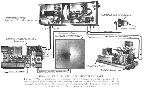
The receiver, of course, may be used with any good low-frequency amplifier and in the photo-diagram in Figure 1 it is shown connected to the General Radio push-pull amplifier, from which excellent results may be obtained, both as to quality and volume of reproduction. The diagram gives complete details for installation with specific recommendations as to the accessory apparatus that has been found satisfactory in tests made in Popular Radio Laboratory.