The Sparton Equasonne Model 301
Reproduced from the September 1929 issue of Radio magazine
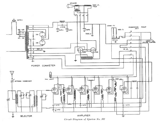
This latest Sparton model is similar to its predecessors except for a few
refinements in coil construction. The receiver consists of three separate and
containing the a-f amplifier. Six Cardon 484 heater type tubes are employed in
the r-f and detector circuits, two '50s in push-pull in the single audio stage
and two '81 rectifiers in the power unit.
All tuning is accomplished in the selector unit which precedes the first tube. This
unit consists of four tuned circuits and is controlled by a four-gang condenser and an
antenna trimmer. The four circuits are conductively coupled by a small section of the
third winding, operating on the theory of the band pass selector. Trimmers are located
on each section of the condenser gang and each circuit is properly balanced before
leaving the factory.
The r-f amplifier unit is untuned, even to the detector. The full responsibility for
selectivity depends upon the selector, allowing the amplifier to be operated so that
maximum gain may be obtained without affecting the frequency of the selected signal.
The idea is not new but is very interesting in the way it has been worked out.
All r-f stages are coupled by r-f chokes, as shown in the circuit diagram. The
"feeder" choke in the plate circuit of the first tube is wound single with
a reversal of direction in the middle, and a resistor is included in series with it in
order to equalize the reactance of the parallel winding. The latter is the primary of another
choke, which is wound like a radio frequency transformer, the primary and secondary being
coupled as tightly as two coils can be coupled. In fact, just as the diagram indicates,
each turn of the primary and secondary lies side by side. This system, of course, is
designed for maximum gain and can only be employed when selectivity in the r-f amplifier
is of no consequence.
The coupling between the second and third stages is accomplished by another paralleled
pair of chokes, although in this case the windings have not been reversed in the middle.
The following two stages are similar to the first except that no
"feeder" circuit has been supplied, the d-c flowing direct through the
primary. The coupling between the last r-f stage and the detector is
accomplished by means of a pair of paralleled chokes in which four reversals are
made, plus an added choke, also reversed, in series with the secondary.
Plate detection is used, the grid being biased by means of a 20,000-ohm resistor in
the power supply. This resistor is replaced with one of 1000 ohms when the
detector tube is used to amplify the output of the phonograph pickup. A 1 mfd
condenser is used to bypass the first two cathodes to ground, while another
condenser of the same size bypasses the remaining three r-f cathodes. The latter
are isolated from the first two by means of an r-f choke. The detector cathode
is also bypassed to ground through a 1 mfd condenser, while the r-f plate lead,
common to all, is bypassed through a 1/4 mfd condenser. An r-f filter is
connected in the output circuit of the detector, and a 50,000-ohm resistor
serves as a volume control by varying the bias on the grids of the r-f tubes.
The power transformer has four secondaries; one supplying three volts to the
filaments of the 484 tubes, one 7-1/2-volt secondary for the '81 filaments and
another for the '50s. The high voltage secondary is wound for 600 volts on each
side. This voltage is rectified by the two '81 tubes and filtered through one p
(Pi) section, the choke of which is shunted with a .15 mfd condenser. The field
coil of the dynamic speaker and another 2 mfd condenser constitute the remainder
of the filter circuit, while a 7000-ohm resistor is shunted across the entire
high voltage output for stabilization.
These curves indicate the relative strength necessary for an interfering broadcast station to produce the same output from the receiver as the station to which the set is tuned. In general, they show that the set tunes more broadly at the higher frequencies than at the lower. First the receiver was tuned to 600 kc and the sensitivity adjusted so that an input of 30 microvolts would give the standard output of 50 milliwatts. Then other signals above and below 600 kc were put into the receiver just as it stood, and the strength of these signals from an oscillator was increased until the same 50 milliwatts output was indicated. The 600 kc curve shows that a signal at 610 kc (corresponding to another broadcast station on that frequency) would require 6000 microvolts energy to produce the output equal to that of the station to which the receiver was tuned. From the similar curves for 1000 and 1400 it will be noticed that on the 1400 kc curve a station 10 kc above resonance (1410 kc), would require only 50 microvolts to produce 100 percent interference. Although this spells disaster to the reception of distant stations within 10 or 20 kc of a local, it need cause no concern for local reception, for local stations have been separated by at least 60 kc. It may be seen that a signal at 1430 kc requires 400 microvolts to compete with the 30 microvolt signal on 1400 kc.
These curves indicate the loss in strength and consequently
in the relative loudness of the various audio frequencies from 100 to 5000
cycles per second when the receiver is tuned to 600, 1000 or 1400 kc. They show
that the low frequencies lose less of their strength than do the high
frequencies. At 1000 and 1400 kc a 1000-cycle note is 3 db less than a 200-cycle
note, and at 600 kc it is 5 db less. The db (decibel) is the unit used for
expressing transmission loss or gain.
For maximum sensitivity this curve shows how many microvolts for each meter
length of the antenna are required at the input of the set to produce an output
of 50 milliwatts, the RMA standard for measurements. The higher curve is the
true record of the receiver's sensitivity if the antenna trimmer were adjusted
when installed as in ordinary practice. The lower curve gives an indication of
the importance of the trimmer, and tells what can be done at the time of
installation.
A change of 1 db is hardly perceptible to the normal ear, and a
difference of 10 db between the highest and lowest note causes little difference
in their quality of reproduction. However, with a difference of 30 db between
the 200-cycle and the 5000-cycle notes of a 600 kc signal, the bass note greatly
emphasized as compared with the treble. This is merely another method stating
that the sidebands are cut more 600 kc than at 1400 kc.
At 1400 kc it will be
seen that 120 microvolts per meter were required. At 600 the gain of the
receiver was great enough to allow the required output of 50 milliwatts with an
input of only 7-1/2 microvolts per meter. In the testing equipment employed an
antenna with an equivalent length of four meters was used so that 7-1/2
microvolt per meter is indicative of a field strength 4x7-1/2 or 30 microvolts.
Sparton's Cardon 484 tubes were unique to the Sparton line and a very few
others, and were similar to the '27 standard type but not the same. They were
replaced with the 485 which was a faster-heating version of the 484. Sparton
also used a 586 tube in place of the '50. The two were virtually identical.
The tuning section of the Model 301 proved to be not selective
enough for use in urban areas where there were many stations. About 1930 an
improved tuner was developed in which there was an additional 484 (485) tube.
This tuner was a decided improvement and could easily replace the original
version by just mounting it on the base-board and attaching the wiring harness
to the power supply terminal board.
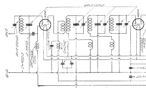
Schematic of the revised Sparton tuner. Note the addition of the 484 tube as well
as the arrangement of the tuned circuits. The adjustment of the antenna capacitor is
very important. It must be reset whenever the antenna is changed. The 484 tube on the
right is the first tube of the RF amplifier, not a part of the tuner section.
Sparton Equasonne models came in a number of variations; all using the same
tuner and RF amplifier sections, but with different power amplifier/supply
units. In some models additional audio amplifiers were added, particularly when
a phonograph was a part of the package.
In the more expensive phono-radio
combinations a push-pull pre-amplifier was added between the detector and the
input of the power amplifier. Strangely, this amplifier used two '26 tubes. One
wonders why they didn't use two more 484's or two '27s. The '26s required a new
power transformer with a 1-1/2-volt filament winding. Of course, the power
section also required a push-pull to push-pull interstage trans-former as well.
Other phono-radio models had a single-stage preamplifier using a 485 or a
two-stage amplifier using two 485s.
Power amplifier sections in the larger
models used type '50 tubes but the lesser models used 182 or 183 Cardon tubes in
push-pull. Both of these has five-volt filaments. They were similar to the '71
and '45 types except for the filament voltages.