Short-wave reception in the 1920's was generally limited to simple regenerative receivers. The only tubes available were triodes and these made very poor amplifiers at higher frequencies. There were, of course, a few superheterodynes for short-wave reception but they were not much better than the regenerative sets. The problem with regenerative receivers, though, was that they acted as transmitters and created interference for other listeners.
The advent of the screen-grid tube opened a new era in r.f design. Here was a tube that would function at the higher frequencies and give greater amplification than any of the triodes.
National introduced a short-wave kit which they called the "National Screen-Grid Short-Wave Tuner." This set came in two, three and four-tube versions, the additional tubes being audio stages after the detector. The basic model has been referred to here as an SW-2 but this was not a factory designation. The two and three tube sets were just called "Thrill Box" but the three-tube version became the famed SW-3. The four-tube version, strangely, was called the SW-4.Thrill Box.
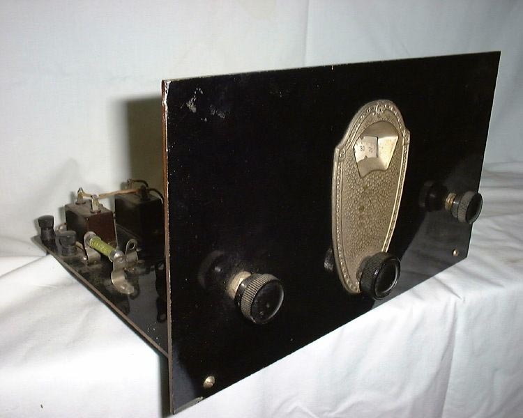
The National Thrill Box, referred to here as the SW-2

National Thrill box

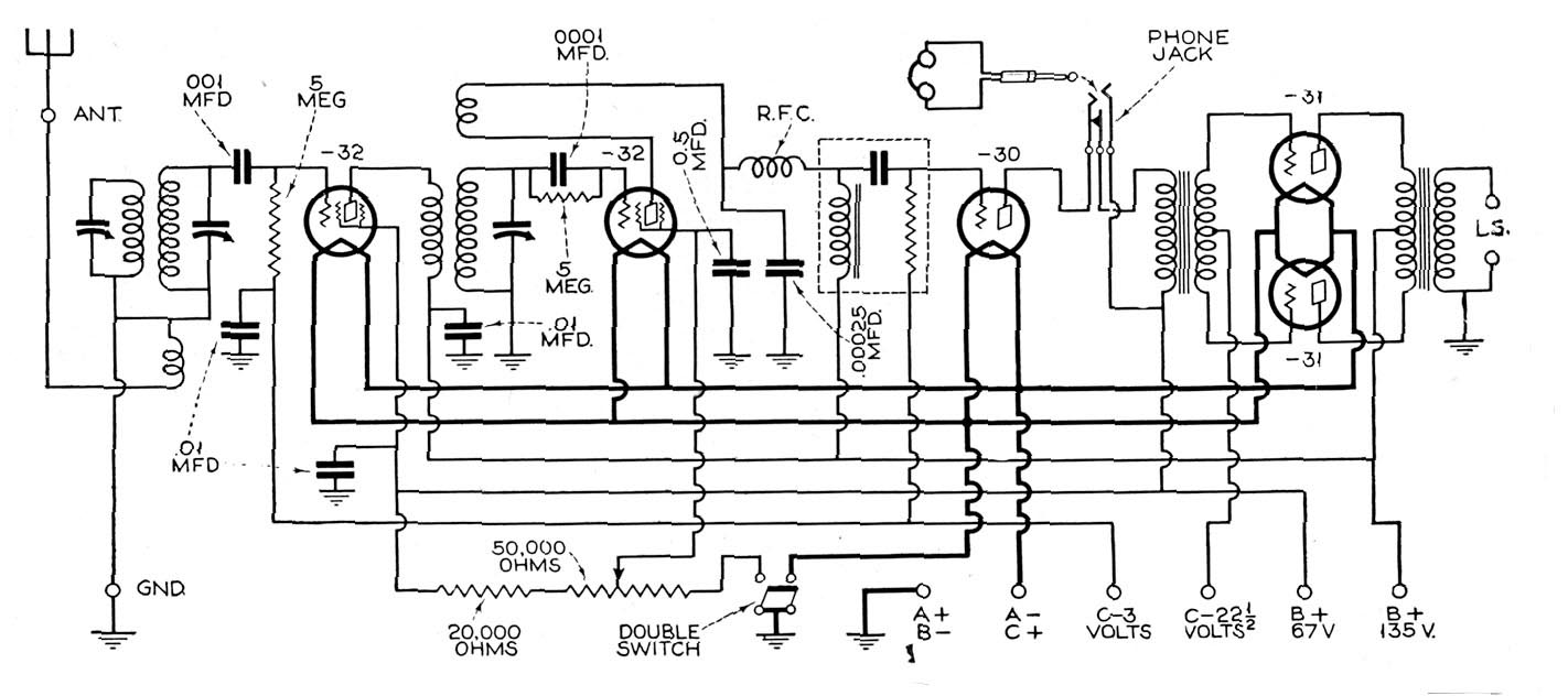
Schematic of the SW-2 Thrill Box. A three tube version was similar but with one audio stage.
The screen-grid tube was added ahead of the triode regenerative detector primarily to prevent radiation from the detector. This stage was not tuned in the grid circuit and therefore did not offer much in the way of sensitivity.
Four plug-in coils were offered which gave the receiver a range of 15.5 to 115 meters. The detector tuning condenser was National's 270-degree SE type which became the standard type used in the later SW-5, SW-3 and other SW-series radios.
Type A, 15.5-26.6 meters.
Secondary 4 turns #14 enamel
Tickler 2 turns #30 DSC
Primary 3 turns #28 enamel
Type B, 23.5-41 meters
Secondary 7 turns #14 enamel
Tickler 2 turns #30 DSC
Primary 6 turns #28 enamel
Type C, 37.5-65 meters
Secondary 14 turns #14 enamel
Tickler 3 turns #30 DSC
Primary 14 turns #28 enamel
Type D, 64-115 meters Secondary 25 turns #18 enamel Tickler 4 turns #30 DSC Primary 25 turns #28 enamel
All coils were wound on two-inch tubing. The secondaries of the first three \
types are spaced eight turns per inch. The tickler is wound in a slot 3/8-inch below the
filament end of the secondary. The primary is wound between the spaces of the secondary
windings.
F 125 mmfd
G1 National #90 r.f. choke
G2 National #10 impedance
M1 .001 mfd
M2 .00025 mfd
M4 .5 mfd
M5 1 mfd
R1 500K ohms
R2 2 ohms
R3 15 ohms
R4 6 megohms
(Note: the original parts list shows the detector tube as a 201A but the schematic shows the 112A. The 201A is probably the correct type)
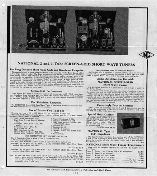
Advertisement that appeared in Radio News

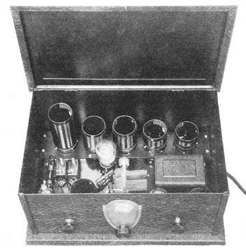
The National SW-4

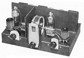
Power supply and amplifier used with the early SW-series receivers

Schematic of the SW-4
This early series of short-wave receivers was superseded by the SW-5 receiver in 1930. Similar in concept, the SW-5 had a tuned r.f. amplifier and a tetrode detector, plus three tubes of audio amplification. The audio system was a two-stage design with a triode stage followed by a push-pull output stage. Like the "Thrill Box" models, the SW-5 also came in several variations, mostly due to tube type changes.
Before the SW-3 there was the SW-5; the numbers indicating the number of tubes used. The SW-5 was developed in 1929 and seems to have been an evolution of the earlier Browning-Drake sets in that it used a one-stage r.f. amplifier followed by a regenerative detector, but now designed for screen-grid tubes and for full-range coverage using plug-in coils.
The initial SW-5 "Thrill Box" is described by James Millen in the June 1930 issue of Radio News. Note the differences in the schematic of the early models; the antenna input system and the method of regeneration control in particular.
The National SW-5

Power Supply for the SW-5


Variations in the circuits of the various models of the SW-5.

Type of tuning gang used in the SW-5 and SW-58 receivers
By James Millen and Robert S. Kruse
REALIZING that before short-wave receivers could come into popular use they must be made to operate with very nearly the same ease and convenience as a modern broadcast receiver, we made a study of their weak points. A receiver was needed that would not only hold its own against any of the older type battery operated jobs for general amateur and experimental reception, but would also meet every requirement of the non-technical owner who, when he felt so inclined, wanted to hear 5SW in London, 2ME in Melbourne, Australia, or any one of a dozen other foreign broadcasting stations without the necessity of waiting for possible re-broadcasts of these stations.
As a result of this survey, the following essentials of a good short-wave
receiver were brought to light:
1—Absolutely hum-less a.c. operation, 2—Single dial control, 3—Loud speaker
reception from foreign broadcast stations, 4—Good tone quality, 5—Non-critical
tuning, 6—Neat appearance.
Most of these problems have heretofore been insurmountable in receiver design. Now, after nearly a year of work on the development of such a receiver in the laboratories of the National Company, in collaboration with a number of well-known short-wave authorities (including, in particular, Robert S. Kruse, who spent a great deal of time both in the National Company's laboratory and in his own laboratory at Hartford, in making investigations into the causes of the various types of hum encountered in such receivers), a new a.c. short-wave receiver has been developed.
While the accompanying illustrations will give a good general idea of the commercial result of this research, the circuit diagram should not be taken too seriously, as all the circuit diagrams in the world mean little, if anything, when it comes to short-wave receivers. In fact, the circuit of the new receiver is to all appearances quite conventional in every way.
When dealing with short waves, it is not so much the diagram which counts, but the manner in which the circuit is used. Little things, like the order in which the tube heaters are wired, the insulation of the bearings in the variable condensers, the type of material used in the coil forms, and so on without end, is what makes the difference between successful design and one which is a failure.
The circuit itself comprises a tuned screen-grid radio-frequency stage, in which provision has been made, if desired, for the use of the heater type pentode tube, where slight additional gain at the expense of selectivity is wanted; a screen-grid regenerative detector; a two-stage transformer-coupled audio amplifier, employing push-pull in the second stage and with provision for plugging phones into the output of the first stage when desired; and a separate power pack especially designed for short-wave work.
Occasionally good hum-free a.c. operation on short waves may be obtained by the mere substitution of the heater type a.c. tubes for the more conventional d.c. types in a standard battery operated short-wave circuit. Such instances, however, are few and far between, as they seem to be the result of an unusually good a.c. line condition, plus a "better than average" set of heater tubes. In most cases the mere use of conventional heater type a.c. tubes results in a quite pronounced and annoying hum that tends to vary somewhat on the different short-wave bands.
Thus, in our work on the development of an a.c. short-wave receiver, we soon found that while we would seem to be securing excellent results on one power line, it was essential that we take the entire outfit to another part of town or to a town in another state which was known to have a particularly poor and troublesome power system, in order to "check and double-check" all results.
After considerable experimentation of the so-called "cut and try" variety, it was found that there were some dozen or so very definite sources of hum trouble to be encountered in the short-wave receiver that would not cause the slightest trouble in a broadcast receiver. It was the identification and the elimination of these concealed sources of hum that finally made possible an a.c. short-wave receiver in which the hum is as low as in a battery powered set. First, the tubes themselves must not only be of the heater type, but also, for complete freedom from hum, must he carefully selected. This is especially true of the detector tube which may be found to be quite noisy when just on the edge of oscillation, unless it is selected with care.
The cause of hum when using some types of heater tubes is apparently due to two things; one being direct leakage across the ceramic insulating column between one side of t he heater and the cathode, and the other to an un-neutralized 60 cycle field around the heater. In general, the -27's, when operated on the verge of oscillation, are less troublesome than the -24's. At first thought this quieter performance of the -27 would tend to recommend its use as the detector. It was soon found, however, that, though more noisy when approaching oscillation, the -24 screen-grid detector was, under practical operating conditions, actually quieter due to its improved sensitivity, eliminating the necessity for full regeneration for the same signal output as obtained with the -27. Improved tone quality was a further by-product obtained from this decreased amount of regeneration.
The second point that must be given careful consideration if successful a.c. operation is to be had, is the power supply unit. This unit should be entirely separate from the receiver itself, completely shielded and located at least three feet from the receiver proper.
It should have exceedingly low inherent hum in its output; (i.e., at least a double section filter using good quality chokes and plenty of condenser capacity must be employed). The power transformer should have an electrostatic shield between the primary and the other windings in order to prevent line disturbances from getting into the power unit and into the set. The rectifier tube must also have an r.f. filter, comprising a radio-frequency choke and by-pass condenser in its output, directly preceding the hum filter. It is this r.f. filter system in the power unit which provides one of the two things necessary to eliminate the so-called "tunable" hum; that is, a hum that shows up only on certain wave-lengths but which nevertheless is quite pronounced. Apparently such hum results from disturbances set up in the rectifier tube itself. Strange as it may seem, separate heater windings on the power transformer seem to give no improvement over the use of a single winding.
The set proper should be completely enclosed in a steel cabinet in order to exclude stray low-frequency magnetic fields. Inci-dentally, these stray fields seem to be the cause of the "a.c." hum frequently encountered with some battery operated short-wave receivers. In order to make the shielding all the more effective, the power supply potentiometer with its associated by-pass condensers should be located inside the set in order to eliminate any external leads which might contain some radio-frequency currents.
It has been found that almost every .5 mfd. condenser of the conventional paper variety now on the market has a materially higher r.f. impedance at the lower wavelengths than a good .01 mica condenser. It is evident, therefore, that even though the cost be slightly more, the use of the smaller mica by-pass condenser will prove more effective and in many instances will completely eliminate a hum that is quite pronounced when using the paper condenser (hum resulting from common coupling through impedance of condenser.)
Along with low impedance by-pass condensers, should also be mentioned center-tap resistors of low ohmic value. That is, they should be of not over 20 ohms, rather than the conventional 60 ohm type employed in broadcast receivers. Furthermore, it will be generally found that a noticeable improvement can he obtained, when operating on a poor power line, if this resistor is of the flat type rather than the round type, which apparently has considerable radio-frequency impedance at the extreme high frequency on which we are working. One side of the center-tap resistor had best be bypassed by one of the small mica condensers previously mentioned.
While the jack for headphone reception is located so as to cut out the final or push-pull stage, there is bound to be a time, especially when listening to some of the foreign stations, when it may be desirable to connect the phones in place of the loudspeaker and use all of the obtainable amplification. But this possible use of the headphones in the output of the complete receiver is not the reason for the employment of push-pull in the final audio stage. Should a single output tube have been employed in place of the push-pull, an unbalanced drain of considerable magnitude would have been imposed upon the power pack, which, in turn, would have produced an infinitesimal fluctuation in some of the bias resistors, resulting in the introduction of hum in the detector and first audio-frequency circuits, which then would be amplified and passed on to the listener, even though the phones were plugged into the first stage jack, and the final stage not in use.
And now comes a method of bum control that will perhaps seem more logical than those already described; that is the location and arrangement of the wiring. As will be seen from the photographs, the receiver is constructed on a metal sub-panel to which is also added a metal bottom shield. By being careful to see that practically all of the radio-frequency leads are located above the sub-panel, while all of the power supply leads are located in the enclosed compartment beneath the sub-panel, much is done to eliminate troubles from so-called modulation hum.
And now for the final and perhaps least expected of all sources of hum trouble-the interstage r.f. trans-former. In order to simplify construction, an attempt was at first made to use a tuned impedance as the interstage coupling device, first as shown in Fig. 7-A and then as in Fig. 7-B, where the stopping condenser is located in the grid return circuit of the detector rather than in the plate circuit of the screen-grid amplifier. In both of these instances the receiver not only lacked the sensitivity obtainable when using a transformer but also suddenly developed a new hum.

Apparently both of these r.f. coupling devices were capable of passing on to the grid of the detector tube some of the hum frequencies developed in the r.f. circuit. The loss of sensitivity was due seemingly to the fact that there is no such thing as an r.f. choke of infinite impedance at all frequencies, which spoiled the effectiveness from a "gain" point of the circuit. The stopping condenser in the grid return circuit at "B" apparently had considerable impedance at some frequencies which also prevented that circuit from performing at par.
The solution is obviously a radio-frequency transformer as shown at "C", Fig. 7 (above), in which not only is the sensitivity of the receiver kept up where it belongs, due to the complete omission of shunt radio frequency chokes and series blocking condensers, but also all low-frequency coupling between any part of the r. f. amplifier circuit and the detector tube grid is completely eliminated.
There are quite a number of regeneration control systems, each of which seems to have some particular short-wave band in which it operates to best advantage. Where the plug-in coils are used, as in this case, to cover an extremely wide frequency range, it is necessary to find some means of regeneration control that will be smooth at all times, and not result in uncontrollable fringe howl, bad hand capacity effects and interlocking.
Of the four most generally used methods, namely, variable plate by-pass condenser, series plate resistor, tickler shunt resistor, and screen-grid voltage control, the screen-grid voltage control method, when accompanied by other circuit details results in uniformly satisfactory performance at all wavelengths.
Tuned Circuits
Good tuned circuits are at the bottom of a good receiver of any sort. Since a tuned circuit comprises a coil and condenser, let us consider both of these units in turn. Until recently there have been no proper high-frequency tuning condensers, designed for that purpose. The practice has been rather to use some sort of a broadcast-range condenser with a few lonesome plates providing the small capacity actually needed. Some improved designs have appeared quite lately, also some of the more recent "vernier" condensers have by good fortune been well adapted to some high-frequency needs and have been much used for such purposes.
One of the early steps taken in the development of the new receiver, therefore, was the design of the special short-wave condenser. Unlike other small tuning condensers it may be mounted in all of the regulation manners-screwed to a panel, screwed to the base or secured to a panel by the hexagon nut on the front bearing in conventional "single bole mounting" style. At high frequencies any condenser with two bearings tends to be noisy, either at once or else after it has bad some use. This tendency can be decreased by the use of a good jumper from rotor to frame and by the use of spring tension to secure good bearing contact. Both devices have in the past been used with varying success. Single-bearing condensers of the "vernier" type, however, are noticeably quieter than 2-bearing types and the difference grows with frequency until at about 60,000 kc. (5 meters) the 2-bearing type has become nearly useless. There are several possible reasons for this trouble. Prominent among them is the effect shown in Fig. 4. The frame and shaft of the condenser form a single-turn coil. As the shaft is turned the bearing contacts change and the single turn is partly opened and closed, tending to produce noises in nearby tubes or those coupled to the condenser. At ordinary frequencies the effect is not serious and therefore need not be worried about, but at high frequencies it is well worth avoiding. The new condenser accordingly uses but one bearing and that bearing is insulated. The connection from the tuned circuit to the rotor is made through a pig-tail of the patented constant impedance type. The pig-tail does not go to the frame, but to a terminal lug on an insulating support at the rear end of the condenser. The stator terminals are close to this terminal, permitting very short leads if desired.


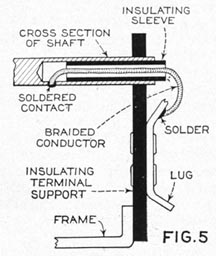
Details of the construction of the tuning capacitors, described above.
The dial appearance alone was not the only reason for the selection. The projection feature eliminates parallax. This dial has two inherent characteristics that make its use particularly valuable in short-wave of the insulated condenser bearing is very important when tuning in on wavelengths below 20 meters.
The new battery type Radiotrons UX230, UX231 and UX232, are ideally suited for use in place of the UY224s and 227s in this new NATIONAL SW-5 "Thrill Box" where A. C. supply is not available. The accompanying blueprints give all necessary data on circuit changes.
A follow-up article on the National SW-5 appeared in the October 1930 issue of Radio News. Written by Robert S. Kruse, one of the designers of the SW-5, it describes the development of the receiver and some of its features in great detail. We may reprint it in a future article on the development of the famous National SW-3.
The SW-5 came in a number of variations, some in the r.f. sections but mostly in the use of tube types and the audio stages. In 1932, for example, the SW-58 appeared. It used type 58 tubes and two 45s in the output stage.


Typical coil used in all of the SW-series receivers

National SW58

The following article appeared in the August 1932 issue of Radio News, written by Zeh Bouck, a frequent contributor of analytical articles. The SW-58 was the final evolution of National's line of TRF receivers. Based on the same circuitry of the SW-45 (an SW-5 with '45 tubes in the output instead of '27's), SW-5, SW-3, and previous SW models, the major difference was in the use of type 58 tubes instead of the '24s used earlier (in a.c.-operated models).
The general tendency toward the superheterodyne in broadcast receiver design has been thoroughly justified by the development of sets meeting the present-day requirement for selectivity at a price that it would be difficult to approach with another system of reception attaining equal results. Probably in the most general interpretation of efficiency-results obtained for dollars spent-the super is without rival in the broadcast band between 1500 kc. and 550 kc. The excellence of the superheterodyne on frequencies higher than those of the conventional broadcast band cannot be denied, but the development of new tubes which greatly enhance the effectiveness of the tuned r.f. system, and several characteristics of the super itself, react unfavorably for this receiver (with the exception of quasi-optical reception) in the general consideration of efficiency as outlined in the foregoing.
From the point of view of amplification, the superheterodyne is fundamentally an inefficient receiver, due to the fact that only about two-thirds of the tubes contribute to signal intensification. As far as amplification is concerned, the mixer or first detector; the oscillator and at least one of the tubes in the preselector may be considered about as useful as the yeriform appendix. It is of course true that the tubes in the preselector circuit function as amplifiers, but it is seldom that they more than compensate the attenuation occasioned in that circuit through the attainment of image-frequency rejection. However, all these tubes contribute to background hiss and noise, which, on short waves, is already of a relatively high level due to causes beyond control. These effects can be reduced in special-purpose supers, such as are used commercially for transoceanic reception, by highly elaborate and expensive design and directional systems. But such tours de force are rarely available to the individual experimenter.
Also, the requirement for selectivity which so adequately justifies the superheterodyne on wavelengths above 200 meters is generally less exacting on shorter wavelengths and is definitely undesirable on television reception. Also, the frequency allocations are more judicious and the channels far less crowded. Between 200 and 600 meters there are 100 ten kc. channels. Between 10 and 200 meters there are 2850 of these ten k.c. channels.
The superheterodyne was originally developed to overcome the inefficiencies accompanying radio-frequency amplification employed fifteen years ago. However, the development of various types of modern vacuum tubes gradually increased the radio-frequency efficiency of short-wave circuits, and the advent of the screen grid made possible a short-wave receiver in which satisfactory r.f. gain was achieved even below 20 meters. The new radio-frequency pentodes contribute still further to the possibilities of the t.r.f. receiver, and the National Company design to be described in this article represents an engineering achievement comparable without apology with a high-grade short-wave super. Until something finer can be developed, this receiver is the ultimate stage in the evolution of a long line of short-wave receivers, the more familiar of which the "Thrill Boxes," the SW-3, SW-5 and the SW-45-have been widely employed for amateur, experimental and commercial purposes.
The principal differences between the present receiver and its immediate predecessor, the SW-45, are best explained by reference to the wiring diagram, Figure 1. These are the substitution of the type 58 pentodes in the r.f. and detector circuits, the provision for radio-frequency gain control and the radio-frequency filter in the plate circuit of the detector.
The radio-frequency pentode has contributed in no small way to the high efficiency of this circuit. Its high amplification factor, transconductance and, above all, its high plate impedance, enable the designer to achieve a degree of selectivity and sensitivity that have heretofore been little more than experimental ideals.
The use of these tubes naturally necessitated the redesign of the plug-in radio-frequency inductors. The primary requisite of such a transformer is to develop as high an impedance in the plate circuit as is possible. In low-frequency work, the optimum ratio between primary and secondary turns is approximately 2 to 3 and represents a compromise between sensitivity and selectivity, taking into consideration capacity, loading effects, etc. As the frequency increases, it has been found that this ratio should also increase, along with the size of the wire and the diameter of the winding. Still further variations are imposed by the r.f. pentode, the 58 having about twice the plate impedance of the 24. The coils, Ti and T2, are wound on the low-loss R-39 material and are available in various sets, covering from 12 to 200 meters, and band-spread coils can be obtained for special portions of the frequency spectrum. Additional coils can be wound, extending the range of the receiver as high as 2000 meters.
It has heretofore been considered that the simple regeneration control in the detector circuit provided adequate overall volume control. Such an arrangement, however, results in several forms of distortion. The radio-frequency tube is necessarily operating at maximum amplification at all times, resulting in considerable overload of both that tube and the detector on strong signals. Backing up the regeneration control to reduce the signal strength results in additional distortion, due to the fact that the detector tube is then being operated with decreased plate or screen voltage. The obvious solution is to employ a second control operating at the input to the r.f. stage.
Under actual reception conditions, this additional control contributes several other advantages. The detector may always be operated on that portion of its characteristic at which best rectification is obtained, with a resulting improvement in tone quality and detecting efficiency. The receiver may also be operated in the condition of maximum selectivity by setting the regeneration control close to the point of oscillation and controlling volume altogether at the r.f. input. This latter feature is of particular utility in bringing in a foreign station having a frequency allocation close to that of a powerful local.
The radio-frequency filter in the detector plate circuit is the result of careful study of the problem. Few experimenters seem to realize the difficulties encountered when excessive r.f. is permitted to invade the audio-frequency circuits. The most noticeable characteristic of such a condition is the presence of hand-capacity effects on all parts of the a.f. system, including the headphones and loudspeaker leads as well as the metal cabinet. Another symptom is the exasperating fringe howl as the detector approaches oscillation. A sticky regeneration control-an apparently excessive amount of lost motion-is directly traceable in many cases to inadequate filtering in the detector output circuit.
The use of a detector tube having a high plate impedance precludes the employment of a fairly large by-pass condenser, which would necessarily attenuate the higher audio frequencies, resulting in muffled tone quality and even unintelligibility of speech. The matter resolves itself into the familiar high radio-frequency problem of an efficient r.f. choke design. A choke which meets the rigid requirements of low-wave work consists of four lattice-wound sections, spaced about 3/16 inch on an Isolantite form. The inductance is only 2-1/2 millihenries, but, what is more important, the distributed capacity has been reduced to 1 mmfd.
Undesirable Coupling Eliminated
The remainder of the circuit is fairly conventional, and the important values are given in Figure 1. Several electrical details, however, are worthy of especial emphasis in reference to the general shielding and the design of the ganged tuning condensers. The obvious shielding between the radio-frequency and detector circuits is shown in Figure 3. However, it has been found that in the design of a single-control high-frequency receiver additional precautions must be taken to avoid coupling between the input and output circuits of the r.f. stage.
Passing over the usual methods of circuit isolation, we come to a point which is often overlooked. This is the coupling through those portions of the tuned circuits which happen to be common in parts of the gang condenser frame. While the paths involved are very short, an inch or so represents an appreciable part of the total conductor length at frequencies above 15 megacycles, and is sufficient to cause instability and circuit interlocking.
To overcome this trouble, the special tuning condenser shown was developed, in which both rotors are entirely insulated from the condenser frame and from each other. This design makes it possible to isolate completely the input and output circuits of the radio-frequency stage, resulting in a perfectly stable system even at the highest frequencies to which the receiver will tune.
Despite the increasing tendency toward unitary design with built-in power supply, the receiver under consideration is constructed for use with a separate power pack. Single unit construction necessitates a large amount of shielding in the r.f. and detector circuits for the elimination of hum, and this excessive shielding, in order to be effective, must be of a different nature than that which amply fulfills the r.f. isolation requirements. Shielding, at best, is a costly nuisance which tends to offset the increased efficiency attained through the use of low loss insulation and careful design. These considerations strongly recommend the use of the separate unit with a high-frequency receiver, limiting the shielding to radio-frequency fields.
The mechanical details of the receiver are fairly obvious from the accompanying photographs.
Rigidity in the radio-frequency circuits is obtained through the judicious use of Isolantite and R-39 supports and mountings. In the design of the dial, consideration was given to the consensus among several hundred amateurs and experimenters who favored a full vision or open scale arrangement. The dial has a scale seven inches long, insuring accuracy in reading. The pointer moves horizontally across the entire length in a linear relationship to the tuning control. The controls shown in Figure 4 are, from left to right, antenna trimmer, radio-frequency volume control, tuning, and regeneration.

The Famous National SW-3


Various versions of the SW-3 from early to late.
Originally appearing in the July 1971 of CQ. magazine And reproduced from the November 1984 SCARS Gazette
By David Stout
Years ahead of its time, the SW-3 revolutionized receiver development and amateur radio. Here is the full story of this amazing set, many of which are still in use today-over 70 years later!
Development of the SW-3
The SW-3 was designed in the late twenties with the idea in mind of developing a product that would have appeal to the radio amateur as well as being adaptable for use by the airlines as a reliable, light-weight receiver for commercial aircraft. In particular. Pan American was looking for such a unit for their early flights to South America. At that time. PAA's feeling was that a radio operator with good C.W. equipment would prove more reliable for long distance, over-water communication than the weighty, cumbersome telephone equipment operated by the pilot and used by other airlines at that time.
The only available receiver that might do the job was the obscure SW-4, a rather cumbersome set designed after a prototype receiver developed in the RCA Van Cortlandt Park Laboratory and manufactured in small quantities by National and Westinghouse. By its weight and size, and the fact that the plug-in coils proved to be ready absorbers of moisture, the SW-4 proved to be unsuited for the trans-oceanic work in the PAA planes.
Little was understood at that time as to why the performance of the SW-4 receivers, using such coils, varied so tremendously with the weather. However, about 1930, the old Boonton Rubber Company became one of the pioneer bakelite custom-molding companies. This company had close connections with the radio industry through a sister company, Boonton Radio Company. The bakelite molding powder sold by the original Bakelite Corporation was based upon the use of wood flour filler which was extremely hydroscopic. Molding, in those days, was done with steam, rather than electric heat and—as a consequence—molding rooms were extremely humid. The coil forms molded by this process varied tremendously in their Q and good and bad coils could be wound on forms that (to the eye) were exactly the same.
In an effort to solve this problem, the Boonton Rubber Co. switched from the old filler to a ground-mica filler and changed over to electrically heated presses. The result was, for the first time, the availability of precision, high-Q molded coil forms that permitted the manufacture of uniform inductors. The new material was used for coils for the SW-3 receiver, and National Co. registered the trademark "R-39" for the forms. The first production run of coils and receivers was made during the summer of 1931.
The SW-3 Design
The SW-3 receiver, manufactured by the National Company (then of Malden, Mass.) is a three-tube set having an R.F. stage, regenerative detector and single audio amplifier. A feature of the receiver is the "single dial control," with R.F. and detector tuning ganged. The SW-3 uses plug-in coils, covering the radio spectrum from 9 to 2000 meters in 10 coil sets. In addition, extra coils provided band-spread for the 10, 20, 40, 80 and 160 meter bands. The receiver is contained within a steel, black crackle finished cabinet measuring about 9" on a side.
During the course of the fourteen-year production run, three basic receiver designs were used. The most popular version, and the one covered in this article, is the A.C. powered version using 2.5 volt glass tubes. A chart is included showing the main differences between the various versions of the receivers, and coil information for the entire SW-3 "family".
The circuit of the SW-3 receiver was developed by the engineers of National Company, with the assistance of David Grimes (ex-W2GKM), at that time the Director of the RCA License Laboratory. The first prototype models of the receiver were built in the home laboratory of James Millen, W1HRX (then W1AXL), in North Reading, Mass. The first production receivers were made during the summer of 1931 and the first advertisements for the new receiver appeared in the fall, 1931 issues of QST magazine.
The very first SW-3 receivers were apparently not made under an RCA license. To limit patent infringement liability, inasmuch as National did not hold an RCA license at that time, the receivers were sold as unwired, and (presumably) were wired by a so-called " Jackson Laboratories" before shipment. The Jackson Laboratories was a dummy company with no assets and was named after one of the streets on which the National Company was then located! (Early SW-3's having the Jackson Laboratories stamp on the shipping carton are a vintage collector's item).
The first version of the SW-3 (Model 1) used an R.F. stage with a type 35 variable-mu tetrode, a regenerative detector using a second 35 tube, and an impedance coupled audio amplifier with a type 27 triode. During the fourteen-year lifetime of the receiver, tube types and components were continually juggled about, but the basic circuitry and layout remained essentially the same.
Within a short time, two more versions of Model 1 receiver were produced. The first version was made for mobile use, employing 6-volt heater type 36 and 37 tubes in place of the 2.5 volt tubes. The second version employed the fragile, microphonic 1.4 volt D.C. tubes (30 and 32) for dry battery operation. Relatively few of these three early Model 1 receivers seem to exist today.
The Popular Model II Receiver
The Model II version of the SW-3 appeared about 1936 and employs the interchangeable 2.5 volt or 6.3 volt pentode tubes, and the circuit of this popular model is shown in the schematic. The R.F. stage uses either a 58 or 6D6 tube, with stage gain controlled by changing the cathode bias by means of the variable control, R1. This potentiometer is mounted horizontally below the tuning dial and is controlled by a thumb dial, conveniently calibrated in signal strength units. An auxiliary tuned circuit (R.F. tuning) permits the R.F. stage to be aligned to the particular antenna in use.
The detector uses a second 58 or 6D6 tube in a plate feedback circuit, with regeneration controlled by a screen voltage potentiometer, R4. The detector is impedance coupled to a 27 or 76 triode audio amplifier which has high impedance magnetic earphones connected directly in series with the plate lead.
Many Model II receivers seem to have been manufactured during the period 1936-1940 and these are the models that turn up most often in today's want-ads.
The Popular Model III Receiver
The final Model III version of the SW3, called the "Universal" model appeared shortly before or after World War II. It uses metal tubes (6J7 and 6C5) and by means of a clever switching system, is convertible to battery operation with the substitution of 1.4 volt octal tubes (1N5 and lA5). Few Model III receivers seem to exist today, and it is not known how many were made. It is surmised that production was slim, as the superheterodyne receiver was becoming increasingly popular at this time, and the regenerative receiver was entering into eclipse.
Table 1 summarizes the various versions of the SW-3, including the numerous coil sets.
The SW-3 Today
Any model of the SW-3 is a collector's item today and the lucky owner of one of these beautiful pioneer receivers will have a pleasant surprise canting to him when he gets it working properly. Considering that the SW-3 was designed before single sideband became a household word, it is amazing to discover how well the little receiver performs in this mode. While the SW-3 tends to be somewhat electrically and mechanically unstable on the highest ranges (10 meters. for example), stability on the lower bands (particularly 160, 80 and 40 meters) is compatible with today's operating demands. The regenerative detector is extremely sensitive and the SW-3 can "hear" as weak a signal as the most modern receiver. To one accustomed to today's multi-stage, multi-tube (transistor) receiver, the quiet background noise and the high earphone level developed by the three-tube SW-3 is quite impressive.
The SW-3 requires a plate supply of about 125 to 200 volts at a total current drain of less than 20 milliamperes. National Velvet power supplies designed for the SW-3 are occasionally available and do the job, provided the old electrolytic capacitors are replaced with new ones. For more stable operation, however, a modern voltage regulated power supply is suggested.
Because the average signal level today is much higher than the level of 1931, the SW-3 exhibits a tendency to overload on strong, local signals, much in the manner of some of today's more expensive receivers. The simple solution to this problem is to insert a 50 mmf variable capacitor in series with the antenna lead at the set, adjusting the capacitance value on a strong signal to reduce the overload condition. Alternatively, the SW-3 will perform wonders on a fifteen-foot wire antenna with less chance of overload than when used with the customary station antenna.
Tuning the SW-3
How many of today's radio amateurs have used a regenerative receiver? (Old Timers can skip this section, as they know by heart the idiosyncrasies of this type of set). Here are some tuning hints for the newcomer and superhet owner.
Today's amateur, used to the direct readout in kilocycles on many deluxe receivers could be at a loss using the uncalibrated dial of the SW-3. One of the first tasks, therefore, is to make a calibration chart for each set of plug-in coils.
The SW-3 requires more operator expertise and know-how to achieve best results than does a modern receiver designed for the appliance operator. There's less circuitry between listener and signal, so to speak, in the old set, and an expert operator can make the SW-3 perform wonders, just as a cowboy can guide his lithe, wiry pinto pony into places where the driver of a luxury Cadillac dare not follow.
Let us begin. The SW-3's sensitivity level is set by the Regeneration control, at the right of the panel. Advancing the control will cause the detector to go into regeneration, at which point a soft plop will be heard in the phones. The R.F Tune (left-hand) control is adjusted for maximum sensitivity also, which occurs at the point where regeneration commences with mini-mum detector screen voltage. Thus, the two controls are adjusted in step until regeneration occurs with R.F. tune control peaked and the regeneration control at the minimum (counter-clockwise setting) that permits regeneration. A few moments listening to a weak C.W. signal will permit this adjustment to be made faster than the time it takes to read about it.
S.S.B. and C.W. signals may now be tuned in the normal manner, remembering that the ear, rather than a non-existent I.F. system provides selectivity, and that all signals have a mirror-image on the other side of zero beat.
The regenerative receiver is ill-suited to a.m. reception as detector sensitivity suffers badly when the regeneration control is retarded for normal a.m. reception. An a.m. signal, however, may be zero-beat in the same manner as an S.S.B. signal for the satisfactory reception.
And now that you have acquired the knack of listening to your treasure—good DX to you!
Where are the 10,000 Receivers Now?
A mint condition SW-3 receiver is a rare gem, indeed. Where did all the 10,000 sets manufactured by National Company disappear to? The majority, sadly, have been junked over the years or cannibalized for parts. However, a sizeable number were tuned to 600 meters and used as auxiliary receivers on the West Coast tuna fishing boats. San Francisco radio stores remember a large sale of 600 meter plug-in coils for the SW-3 about the time radio amateurs traded the regenerative receiver in on the new super-heterodyne sets.
Interest among radio amateurs is reviving in this wonderful radio receiver, and those SW-3's showing up in want-ads are quickly snapped up by collectors. This little receiver still occupies a warm spot in the heart of many old-time amateurs who worked their first DX with this magic, black box of tricks, so many years ago.
During the long, useful life of the SW-3 receiver, over 10,000 units were built and the set was used by amateurs, commercial stations, airlines, ships and uncounted expeditions as a compact and wholly reliable receiver. Even today, the SW-3 is still in active service and doing a good job of coping with today's complex communication problems!
Where are the 10,000 Receivers Now?
The author wishes to thank Mr. James Millen, WIHRX, of the Millen Mfg. Co., Malden, Mass. for much of the background material contained in this article.Table 1
Variations In SW-3 Models
SW-3 Model One
Version I: Uses 24, 24, 27 tubes and color-coded coils. An audio volume control potentiometer is used instead of an R.F. gain control. Uses "10-20" series coils.
Version II: As above, but with 36, 36, 37 tubes and B+ switch for mobile operation. Later models incorporated R.F. gain control. Uses "10-20" series coils.
Version III: Uses 32, 32, 30 (2 volt D.C.) tubes. Incorporates B+ switch. R.F. gain controlled by antenna coil potentiometer. D.C. bias supply required. Uses "10-20" series coils.
SW-3 Model Two
Uses 58, 58, 57 (2.5 volt) tubes or 6C6, 6C6, 76 (6.3 volt) tubes. Uses "60" series coils. The schematic of this popular receiver is shown above.
S W-3 Model Three ("Universal")
Uses 6J7, 6J7, 6C5 (6.3 volt) tubes or IN5, 1N5, 1A5 (1.4 volt) tubes. Incorporates A.C./D.C. filament switch standby switch, earphone jack (some models) and bias resistor in B-minus return. Uses "30-40" series coils.
Note: The only apparent difference in the various coil series is the number of turns in the feedback ("tickler") coil. Many coils are interchangeable between the different receivers. The tickler coil may be easily rewound, adding or subtracting one or two turns to make one style of coil work in a different receiver design. Tickler winding should permit regeneration to occur with control potentiometer set at about mid-point.
NOTE: Actually, the National Model SW-5 was a direct forerunner of the SW-3. The first SW-3s were designed to use standard SW-5 plug-in coils. QST magazine for the years 1929 through 1931 clearly documents the rise and fall of the SW-3, 4 and 5 models in the content of its advertisements. In addition, a fine article on the SW-5 by Robert S. Kruse is on pages 17 through 22 of QST for January 1931. A good technical article on the SW-3 by James Millen can be found on pages 9 through 16 of QST for September 1931.
Table 2-SW-3 Receiver Coil Data
(Early SW-series receivers used the colored coils)